
Build a Line-Following Robot: Arduino Tutorial for Kids
Ever wanted to build a robot that can drive itself? In this exciting hands-on tutorial from AI Valley, the top robotics institute in Zirakpur, you will build a real line-following robot that uses infrared sensors to follow a black line on the floor — just like the robots used in factories and warehouses!
🎯 What You'll Build
A small robot car that uses two IR sensors to detect a black line on a white surface and automatically steers itself to follow it. When the line curves left, the robot turns left. When it curves right, the robot turns right. It's like giving your robot its own pair of eyes!📋 Prerequisites & Materials
Step 1: Assemble the Chassis and Mount the Motors
Start by attaching the two DC motors to your robot chassis. Most kits come with mounting holes. Secure the motors with screws, attach the wheels to the motor shafts, and add a caster wheel (or ball wheel) at the front for balance.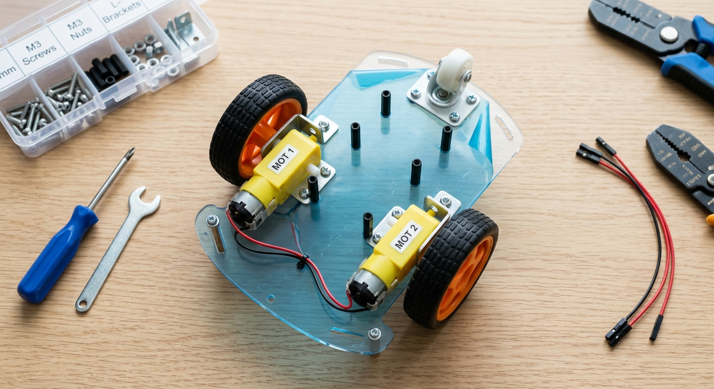
A top-down photo of a robot car chassis with two DC motors mounted
Mount the Arduino Uno board on top of the chassis using screws or double-sided tape. Place the L298N motor driver next to it.
Tip: Label your motors as "Left Motor" and "Right Motor" — this will help when writing the code!
Step 2: Wire the Motor Driver to Arduino
The L298N motor driver acts as a bridge between your Arduino and the motors. Arduino sends small signals, and the motor driver amplifies them to spin the motors.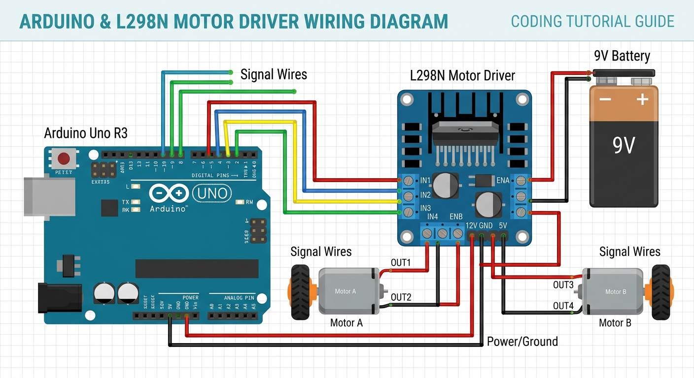
A wiring diagram showing connections between Arduino Uno and L298N motor driver
Important: Double-check every wire before powering on. A wrong connection could damage your Arduino!
Step 3: Connect the IR Sensors
IR sensors work by emitting infrared light and measuring how much bounces back. A white surface reflects lots of light (HIGH), while a black line absorbs the light (LOW). Mount the sensors at the front of your chassis, pointing down, about 1-2 cm above the ground.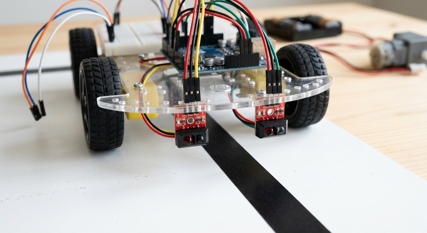
IR sensor modules mounted under the robot front, pointing at the floor
Step 4: Write the Brain — The Arduino Code
Open the Arduino IDE, create a new sketch, and paste this complete code: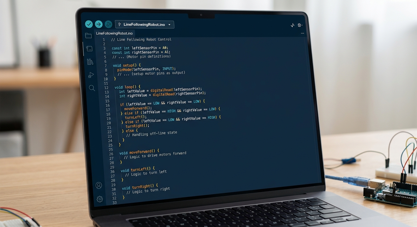
The Arduino IDE showing the complete line-following robot code
What this code does: The loop() reads both sensors continuously. Based on which sensor detects the black line, it decides to go forward, turn left, turn right, or stop.
Step 5: Create the Track and Test!
Use black electrical tape on a white floor to create an oval track. Start simple, then add curves.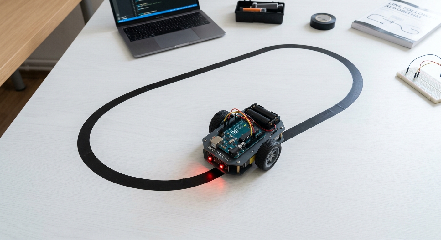
A robot car following a black tape track on a white floor
- Connect the 9V battery to the motor driver
- Upload the code to Arduino via USB cable
- Place the robot so sensors straddle the black line
- Open Serial Monitor (Ctrl+Shift+M) to debug
- Watch your robot drive itself!
Troubleshooting:
🎉 Final Result
Congratulations! You've built a real autonomous robot that navigates a path using infrared sensors. You've learned motor drivers, IR sensors, digital I/O, and control logic — the same fundamentals used in industrial automation!🚀 Challenge: Take It Further
analogWrite() for smoother steering